Contrails ! Jabiru lube fix # 2
New data
In addition to the tests conducted by Martin L and Alexandre Patte from Jabiru France, Contrails !, along with Marc Béranger, gathered some additional data on the lubrication of the Jabiru 4-cylinder hydraulic lifter engine.
To improve top end lubrication, Marc adopted a particular approach.
Please note : This is not an official recommendation from Jabiru, but the personal investigation of a private Jabiru 2200 owner.
Variation on a theme
Improving oilflow
Thanks to Martin and Alexandre Patte's experiments, we know that the oil feed to the cylinder heads is limited on the Jabiru, by a restriction at the engine block.
The oil sqeezes around the restrictor plugs, then enters the oil tube to the heads via a groove and oil hole in the plug.
As shown here, the oil flow can be improved by directly drilling the restrictor plug.
The oil leak between the restrictor plug and its bore must correspond to very close tolerances.
In order to ensure adequate valve gear lubrication, the leak around the restrictor should be equivalent to a 0.5 mm diameter orifice, i.e. a 0.196 mm² area.
This is equivalent to a 5.7 μm (0.22 thou) diametral clearance around an 11 mm plug, less than 6 microns !
Marc's solution
Needless to say such a clearance can only be obtained by accurately matching parts and testing oil flow during engine assembly.
It seems much simpler - and more precise - to ensure the oil flow directly by drilling.
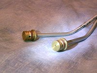
To better control the oil flow, Marc elected to turn new restrictors with no peripheral clearance nor groove, in which the oil will flow only through a center bleed hole.
Those new brass restrictor plugs were brazed directly onto the oil tubes, just like the original ones.
Preliminary study
Calibrated orifices flow test
To measure oil flow through calibrated bleed orifices, each restrictor was clamped at the end of a graduated plastic hose of known capacity.
It is a matter of timing the flow of a known quantity of warm oil under 4 bar air pressure, corresponding to the main oil circuit pressure in the engine.
Before each test, Total Aero DM oil is warmed up in a water bath, to ensure a realistic fluidity.
The actual oil temperature is about 40°C, corresponding to engine oil temperature after a few minute ground run.
What the picture doesn't show are the scrolls of "smoke" escaping from the pan...
Video : oil flow tests
Measurement of oil flow through calibrated restrictor orifices
For each orifice diameter, we timed the flow of a known volume of oil under 4 bar pressure, and then computed the flow in cm³/min.
We compared our electronic timing with the operator "voice" timing, which proved reasonably accurate (turn audio ON).
The dark oil level can be clearly made out in the transparent hose.
Results
To avoid drilling multiple orifices, we measured the flow corresponding to 3 different diameters.
| Diameter (mm) | Oil flow (cm³/s) | Oil flow (cm³/min) |
|---|---|---|
| 0.5 | 0.68 | 41 |
| 0.6 | 0.89 | 53 |
| 0.8 | 3.20 | 192 |
Oil flow appears to be roughly proportional to the square of the diameter, hence proportional to orifice area.
To obtain oil flow into individual heads, those values must be divided by 2.
Observations
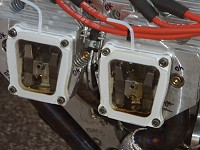
Clear rocker covers
Marc fabricated a complete set of clear rocker covers with perspex glued with cyanoacrylate.
They were gas tight during the first tests, then drilled and equiped with vent tubes.
Original configuration
After sitting for some time, the front and rear rocker chambers only show oil traces.
In the original configuration, it was observed that it takes several minutes after startup for oil to reach the front cylinder heads.
On this taildragger, the rear heads always get more oil than the front ones when on the ground..
Althoug some oil is seen in the rear rocker chamber, the amount seems less than adequate.
Need for venting
During the tests with different orifice diameters, the absence of rocker chamber venting seemed to disturb oil distribution and return to the crankcase.
Interpretation : the area of the return passages to crankcase being limited (see below), the pressure equalizing between crankcase and rocker chambers cannot occur when too much oil obstructs the passages.
The research for the best compromise was continued with vent tubes open.
Upper flow limit
Oil return to crankcase
Oil flow to the cylinder heads is limited by two considerations :
- Oil pressure in the main circuit must not be affected.
- The return passages to crankcase must be large enough to accomodate the aerated oil larger volume and gravity only return.
We made a test with a 0.8 mm diameter hole into one of the original restrictor plugs.
As expected because of the reasonable oil flow, oil pressure showed no change.
Nevertheless return oil passages are not not large enough, and the rocker chambers fill up with oil within seconds after startup.
The oil supply orifice must therefore be smaller than this value.
Video : oil rising in rocker chambers
Orifice 0,8 mm.
Despite the poor quality of the video, one can see the oil level rising in the rocker chambers within twenty seconds from startup.
Here only the front chamber is vented, hence the relative stagnation in the rear head where air is trapped.
This tends to indicate that instead of machined passages, the oil may be returning back to the sump via clearances around the lifters at the bottom of the shroud tubes.
Choosing the best compromise
Choice of bleed orifice
Owing to the limitations in bleed orifice diameter, a 0.5 mm drilling seemed a good compromise : the oil flow looks definitely better than in the original condition, while staying away from rocker chamber flooding.
Although the rear heads seem better fed, oil flow is visible shortly after startup in all four heads.
Influence of RPM
Please note that the rocker chambers are now vented.
Several ground runs between 1400 and 2400 RPM did not show any pressure or oil flow variation in the heads.
Symmetry
No noticeable difference between righ and left sides, see pictures.
Oil flow measurements on the aircraft
Method
Visual observations were supplemented by actual flow data.
Measurements were conducted using transparent tubing and a measuring cylinder graduated in cm³.
They consisted in diverting the oilflow from each pair of heads for a moment.
No problem with running the heads dry : the duration of a test, less than 3 minutes, is shorter than the time needed for oil to reach the heads during a cold start (several minutes with the original configuration).
Due to the limited oilflow, each measurement was conducted in two phases with no interruption :
- timing the filling of the transparent tubing
- then timing the flow of 10 cm³ of oil into the graduated cylinder.
Total volume at each test : 26 cm³
Results
Oil flow numbers
Oil Total Aero DM, pressure 5 bar, temperature 50 to 60°C, engine speed 1200 to 2400 RPM.
| (Martin) | Origin | 0.5 mm orifice | |
|---|---|---|---|
| Right | (8.4) | 4.7 | 18.9 |
| Left | (8.4) | 4.8 | 18.6 |
| Martin's initial numbers shown in parentheses for comparison | |||
It can be seen that on Marc's engine (30 hrs since new), the initial oilflow amounts to just 57 % of Martin's engine original flow.
It appears that with the chosen 0.5 mm bleed orifice, the oilflow is increased 4 times (390 %), while avoiding overflow problems.
Flight tests
Marc conducted some flight tests with open rocker chamber vents.
- Oil leaks
- No leak nor oil traces under the cowling.
- Temperatures
- Oil temperatures are now about 20°C higher than before the mod (the airplane has no oil cooler), while head temperatures are noticeably lower :
- Oil : 80-100°C
- Heads : 140-160°C
To learn more
Articles on Contrails !
- Jabiru rocker lubrication


- Martin's article on his Jabiru valve lubrication problems
- Jabiru lubrication fix # 1


- Martin's fix to his lubrication problem
Websites
 Jabiru France
- French Jabiru dealer Alexandre Patte's website
 The Rest of the Story
- A well documented article on Lycoming valve lubrication by Marvel & Scott. Quotes hard to come by cylinder-head oilflow data.
 Send an email


