- Home
- Airframe and structure
- MCR 4S Defogging system
Contrails ! MCR 4S defogging system

Windshield defogging
Not every flight is performed on a hot summer day.
The IF-Team experienced humidity, drizzle, fogging during the second flight.
On a cold damp day, the windshields sometimes fogs up until the lining up on the runway.
After some years flying "just like that", we decided it was time to install a correct defogging system.
Blower installation
Principle
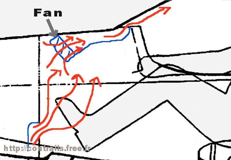
The principle is the same as in cars : a fan and a moulded duct to blow warm air from under the panel turtledeck through adequately sized holes at the foot of the windshield.
Due to the efficiency of the cabin heat there is a warm air "bubble" behind the panel, that was of no use to this date.
Fan

The starting point was a 80 mm PC fan from a computer scrap box at CERN in Geneva.
In spite of a very quiet (!) running, the critter did not seem to blow that much.
Igor conducted a little study : PC fans come in several sizes, 70 mm, 80 mm, 125 mm, in 2-wire and 4-wire versions.
The specialists kindly advise that the most powerful fans are also a little noisy...

His son Robin, resourceful as always, found in a PC shop a 95 mm diameter fan drawing 0.38 A and blowing fairly well.
The composite duct will be adapted to the larger diameter.
Composite duct
On-airplane design
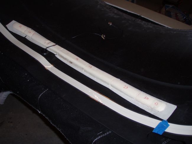
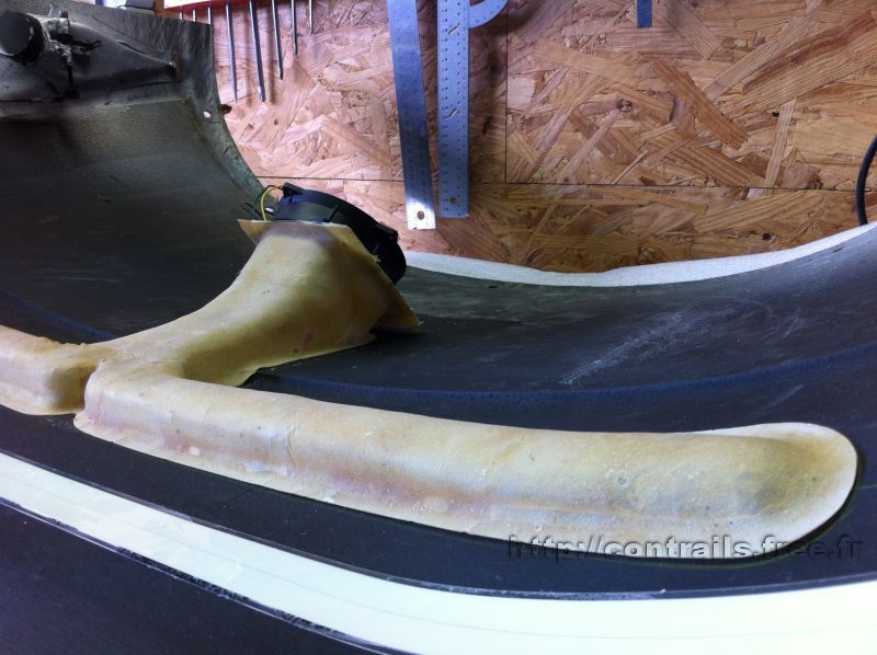
According to the IF-Team High Technology technique (IFTOAD), Igor carefully noted the instruments size and position behind the panel, then started to lay polystyrene blocks sticked with double face tape under the turtledeck to fabricate the lost mold.
The turtledeckis the carbon fiber part that closes the top of the fuselage from the instrument panel up to the firewall. It is very easy to remove on a MCR, providing easy access to the the instruments and back of panel.

As a PC fan is not very powerful, the duct is carefully shaped to minimize pressure drop.
The white strip in the foreground is the backup instrument lighting electroluminescent strip..
One can also see the GPS antena fixing nut and coax.
Fiberglass lay up
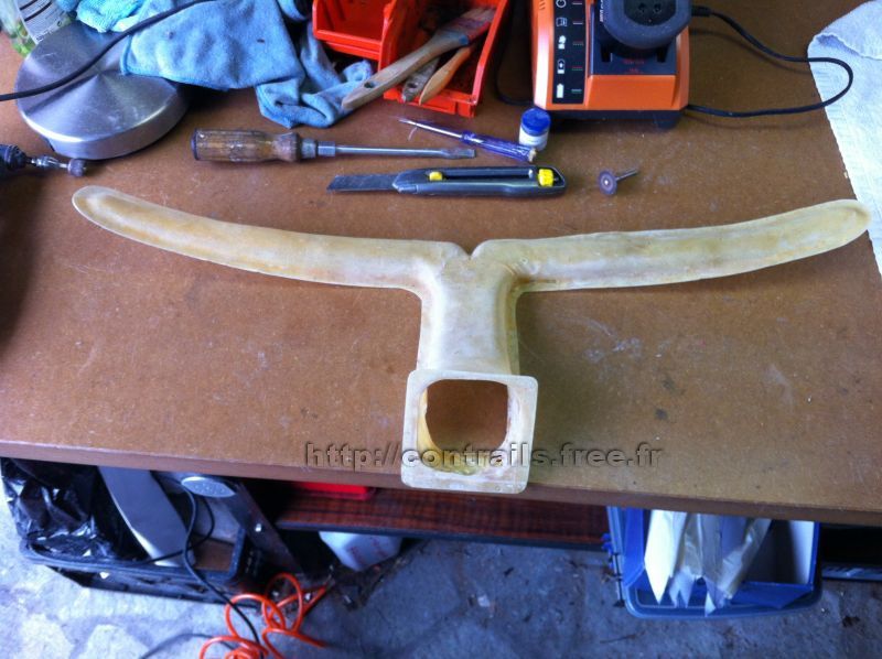
The polystyrene form is covered with brown packing tape to prevent sticking.
The glass/epoxy layup is perform in one pass, with two thin cloth layers and peel ply.

Installation
Calibrating the holes

The open upper side of the duct is sealed with duct tape, and different hole sizes are tested, to obtain a correct airflow across the width of the windshield.
Note that the hole diameters must vary to equalize the left/right distribution.
Due to the turtledeck profile, the duct cross section is larger on the left, thus privileging the pilot side.
Turtledeck drilling

The turtledeck is drilled according to the tests.
Before bonding, Igor performed a trial assembly and blow test (see the 12 V bench power supply).
Note that the turtledeck holes are visible through the translucent glass fiber.
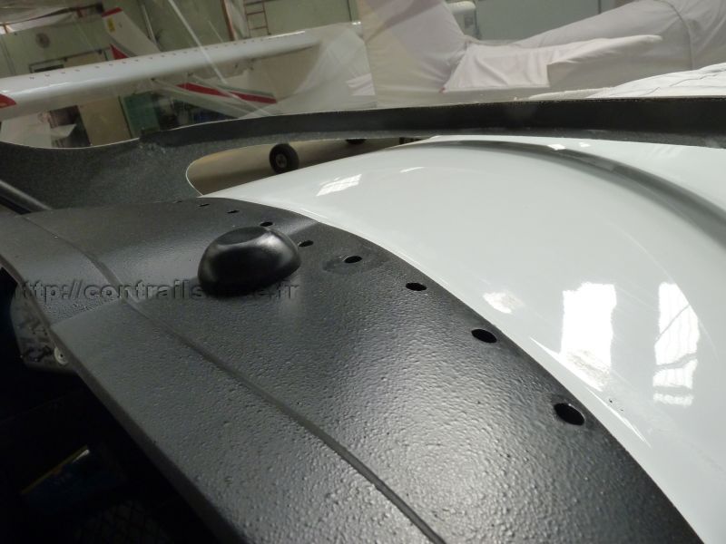
The holes viewed from outside. The inside of the duct and the edge of the holes are painted black.

The holes open just at the foot of the windshield.
Bonding to the turtledeck

The duct is bonded with epoxy under the turtledeck.
It is held in place with tape during the glue setting.
Sealing is provided with a layer of soft foam between the fan and the mounting plate.


Electrical layout
Wiring

The fan is fed from the main bus bar, through the "Panel light" fuse, which we confess is not used very often...
To take into account the additional current draw of the fan, the fuse rating is increased from 2A to 3A (AWG 22 wires are rated for 5A continuous).
Of course the wiring diagram was updated on the same day !
Illuminated switch

A space had been provided on the panel from the start, so installing the switch is straightforward.
Just for the fun, the switch will be of the "illuminated" type, with an LED in the lever, to avoid forgetting the fan in cruise.
Is this really useful ? Well let's say that the little blue light looks so cute ;-)
Tests
Efficiency
A first test yielded a correct airflow.
Of course since the installation, the weather has been fine ;-)
Defogging tests are postponed...until the next rainy days.
Three years later (2016), some pictures...
The fan is not very powerful, but adequate on the ground (at takeoff, the remaining fog disappears).


Defogging with cold engine (efficiency is dependent on the cabin heat)
1 minute interval
The left part of the windshield - in front of the pilot - is quickly cleared up.
 Contact the author
