Contrails ! Rotax 914 fuel pumps
Rotax change of mind 
The Rotax 914 engine has no mechanical fuel pump, but two electric pumps, to be installed by the homebuilder.
The Rotax manuals are puzzling : the current documents give two different configurations.
The Rotax saga
Installation Manual
In the Installation Manual (1996-05-10), Rotax shows on page 48, a parallel setup, curiously lacking check valves.
A note on page 51 sheds some light : "There is no need for a check valve for the operation of the two electric fuel pumps since the pump itself won't allow any passage against correct direction of flow".
Maintenance Manual
The page 32 in the Maintenance Manual (1997/02/01), gives now a seemingly series installation, with check valves in parallel.
Would the pumps now be more or less transparent to the fuel flow ?
Not sure : one can see that this setup is not really in series. The fuel can flow around each pump via one of the check valves.
Operator's Manual
The Operator's Manual shows on page 9-2 (Dec 01/98), the same "series" mounting.
Rather surprisingly, Rotax did not publish any Service Bulletin on the subject, and the Installation Manual is still current. The "series" installation is by no means mandatory.
"Series", parallel, and why ?
The Pierburg pump
What does the pump manufacturer say ?
It is always wiser to refer to the equipment manufacturer. The Pierburg website is very clear on many points. Here is a brief summary.
Specifications
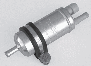
The electric pumps of the Rotax 914, are self-priming, positive displacement, vane type E1F models (p/n 7.21440.78.0).
This model is ubiquitous in the automobile world, as original equipement as well as aftermaket parts.
| Body diameter : | 38 mm |
| Static pressure : | > 1.85 bar |
| Volume flow : | 95 L/h |
| System pressure : | 1 bar |
| Suction head : | 500 mm maxi |
| Rated voltage : | 12 VDC |
| Current draw : | < 4.3 A |
Precautions of use
Pierburg states the following :
- The pump is cooled and lubricated by the fuel flow. It must not run dry.
- Running dry will cause rapid failure of the pump (30 seconds max, but pumps should basically never be allowed to run dry).
- A proper fuel flow must be provided to insure adequate cooling.
- Suction head is best avoided, and should not exceed 500 mm.
- A return line to the fuel tank should be installed.
- A 60 to 100 μm mesh filter of suitable surface, must be provided upstream of the pump. Paper filters are not suitable.
- For use in Diesel vehicle, the pump inlet built-in prefilter must be removed.
- This built-in prefilter must be in place for use with gasoline. It can be carefully pulled out for cleaning. Built-in prefilters are not available as spare parts.
- Suction or flow delivery from one pump through another electric pump is not possible.
Recommended setup
Pierburg suggests two different setups for redundancy.
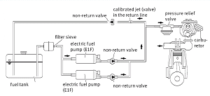
Parallel with check-valves
Pierburg recommends a parallel layout with check valves. For cases where safety of fuel supply is important, the pumps are controlled separately.
Note the return line to the fuel tank, to insure proper cooling flow through the pumps.
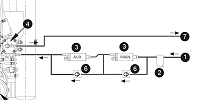
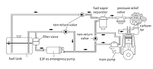
"Series/parallel"
Pierburg also shows a system with a backup pump and check-valves, so that both pumps can draw and deliver freely.
We recognize the "a la Rotax" installation.
Pierburg seems to have studied this case to add redundancy to an existing installation.
Discussion
Why electrical pumps on the 914 ?
Normally aspirated Rotax engine run on a mechanical pump without any problem.
On the turbocharged 914, the operation of the TCU demands a fuel pressure 0.25 bar above airbox pressure.
One may assume the electric pumps are needed for their higher delivery pressure.
Their smoothness of flow, as compared to the pulsation of the mechanical pumps, may also play a role.
Series setup
In the series layout, the flow delivery is the same as with only one pump. The delivery pressure is approximately double.
Please note : if one of the pumps stops, the fuel flow stops, as a positive displacement pump is not transparent.
The series layout cannot insure fuel delivery redundancy. The reliability is less, as the higher part count increases the probability of failure.
Parallel setup
This setup should call for check valves. The flow is approximately double, while the pressure is the same as with only one pump.
The parallel setup insures redundancy : any of the two pumps can independantly feed the engine.
This layout is logically recommended by Pierburg.
Series/parallel or a la Rotax
Contrary to what appears at first glance, this is not a series installation.
When operating alone, each pump can feed the engine independantly, via the corresponding check valve.
When operating together, the pumps insure a higher delivery pressure, like in the series setup, which can be of interest at altitude.
This setup seems satisfactory, despite its tortuous appearance.
Failures
"Fault tree" analysis
Before making decisions, one must analyze every possible failure mode, even the most remote. Here are a few examples.
Loss of electrical supply : the pumps must be fed by truly independant electical sources. By the way, the electrical circuit proposed by Rotax leaves much to be desired.
Stoppage of one pump : No problem with the installation in parallel, or a la Rotax : the other pump insures fuel delivery. With the series setup, the engine stops. It should be avoided in an aircraft.
Destruction of one pump, with debris : In parallel, no problem, the second pump is independant. There is a slight chance that the debris jam the broken pump check valve in the open position, hence a lower delivery pressure due to the leak. Note that the broken pump, once stopped, is not really transparent to fuel flow, which will limit unwanted backflow.
Maximum engine output might not be maintained.
The clogging of the broken pump check valve poses no problem.
Setup "a la Rotax" : if the upstream (main) pump sheds debris, chances are great that the debris clog the other pump inlet, with loss of redundancy. The blockage of the downstream check valve in the open position may lower the delivery pressure, as in the parallel case.
Conclusion
The parallel and series/parallel layouts seem satisfactory.
The Rotax setup, apart from its complexity, seems to present some risks that are eliminated with the classical parallel-plus-check valves setup.
The choice
Responsability of the homebuilder
It is up to the builder to make pump installation decisions.
What we did on the MCR 4S
All the above considerations were submitted to the French Rotax importer, Avirex.
They could not find any reasons to choose the complicated Rotax setup against the parallel installation suggested by Pierburg.
So the proven parallel setup seemed the layout of choice. Our plumbing includes an automobile prefilter on each tank line, and an Andair gascolator with a PTFE coated 70 micron screen upstream of the pumps.
The aircraft was tested up to FL 145, from -14°C to +37°C, without any problem.
More on Pierburg fuel systems
Pierburg documentation
 Service Information : fitting an electrical E1F fuel pump (166 ko)
 Service Information : Pierburg fuel check valves (204 ko)
 Service Information : clogged Pierburg built-in prefilter (127 ko)
 Pierburg fuel systems (952 ko)
MSI/Pierburg/Kolbenschmidt website
 Catalogs on Motor Service International/Pierburg website
 E-mail me




 Previous
