 Contrails ! Inside a Jabiru
Anatomy of the Jabiru 3300
Jabiru engine lovers will enjoy this little "journey inside a Jabiru".
Those Jabiru 3300 and 2200 pictures were provided to Contrails by Pete Krotje from Jabiru USA Sport Aircraft, and Jabiru owners, and are published here with their kind permission.
The 4-cylinder Jabiru 2200 technology is quite similar to that of the 3300.
Jabiru 3300 6 cylinder tear down
Bottom end
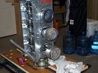
Note how the engine is secured vertically on the bench with two bolts through the propeller flange. The Loctite 515 tube is for sealing the crankcase.
Near the top, the mechanical fuel pump pushrod protrudes from the crankcase.
Further down are the pushrod holes and and oil orifices to cylinder heads.
At the bottom is the oblique oil pump pickup tube with its skewed end.
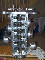
The fully machined crankcase splits vertically.
At the top of the camshaft, in front of the #6 piston, the fuel pump eccentric and its pushrod passes through the right crankcase half.
This model has solid lifters. The oil return holes machined in each lifter housing are clearly visible.
The top cylinder has one of the through-bolts holding the crankcase half and the cylinder base flange.
At the bottom is the oil filter adaptor with its thread and the oil pressure relief valve nose, washer and retaining ring.
The main oil gallery runs down the length of the left crankcase half at the level of the cylinder head lubricating holes.
Crankcase
Matching crankcase halves are fully machined from solid light alloy. The machining is fine.
A serial number can be made out in the #1 piston passage in the right crankcase half. See also the oblique oil pickup tube.
The crankcase has 7 bearings. The #1 bearing shows the recessed thrust bearing washer housing.
Note the positioning dowel at each through-bolt passage. Sealing is with O-rings in grooves machined in the dowel bores.
Note the waisted through-bolts (10 long, 4 short, 2 very short), and the intricate oil passages to the main bearings.
Looking closely at the lifter housings, the pressure lubrication holes and oil return holes are visible.
The camshaft bearings seem to be splash lubricated.
Moving parts
Camshaft
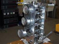
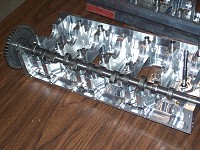
The camshaft installed in the left crankcase half.
The 7 journals and 6 pairs of cams are clearly visible.
At the rear near the timing pinion, the fuel pump eccentric is located between the two #6 cylinder cams.
Also note the two thrust bearings machined in the camshaft near the pinion.
Crankshaft
The hollow crankshaft is machined out of solid 4140 chrome molybdenum alloy steel. It features 7 main bearings (48 mm diameter). There is a double bearing for the propeller.
The steel shell bearings are of automobile type. The generous oil holes in the crank pins and main bearings are visible.
Lubrication of the big ends is ensured by oblique channels drilled from main bearings # 2, 4, 5, 7, the bearing shells of which have a groove and hole. The #1 bearing shells have no hole, as the oil is fed via the hollow crankshaft main bearing.
The crankshaft seems very light and its finish is outstanding.
Hollow 45 mm diameter crank pins have plugs closing the oil circuit.
Thrust faces are machined at the front of the crankshaft and the front face of the #1 crank throw. They bear on thrust bearings housed in recesses in the crankcase.
Each crankshaft end takes a lip seal. Those seals are removable without splitting the engine.
The propeller flange is removable to give access to the front crankshaft seal.
Pistons
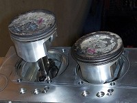
The slipper type pistons come from General Motors Australia.
The very short pin is floating and maintained by circlips in re-machined grooves in the bosses.
The classical 3-ring set includes two cast iron top rings and one expander-type scraper.
Note how the piston passages in the block are narrow, ensuring better crankcase rigidity.
Connecting rods
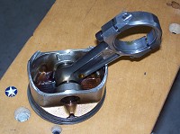
The I-section connecting rods are machined from 4130 alloy steel.
The big end caps are tapped for 1×5/16 UNF screws, so disassembly implies removing the pistons and splitting the crankcase.
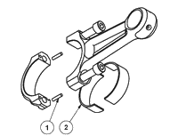
Matching big end caps are positioned with two 3×14 dowels [1].
The steel shell bearings [2] (45 mm diameter) are of automobile origin.
 Top end
Cylinder heads
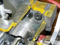
The heads are machined from solid aluminium alloy.
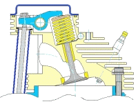
The combustion chambers are wedge shaped, with the spark plugs located on the thick side.
Note the squish surface (see below) with an "X" mark.
The wedge shape gives a very compact combustion chamber.
This arrangement results in parallel valves, with inlet and exhaust ports on the same side.
The head shown here is from a Jabiru 2200 4-cylinder engine.
The different diameters of the shrunk in seats are visible : smaller exhaust on the left, larger inlet on the right.
One can clearly see the turbulence generating squish surfaces below the spark plug holes and above the ports.
Please note that the finning is larger on the exhaust side, as thermodynamics dictates.
Valve gear
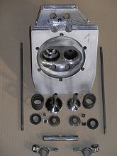
The picture shows the valve gear components.
The parts are the same as in the Jabiru 3300 6 cylinder engine.
Below the head are the valves with their single coil spring (40 mm long), spring seat washer, spring retainer and split collets.
In the forefront are the two manually adjustable rockers (solid lifters) and their 12 shaft.
Rocker pushrods are visible on each side.
Valves and guides
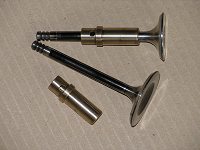
The valves are manufactured in England for Jabiru.
Stem diameter is 7 mm, and head diameters are 33 mm exhaust, 41 mm inlet.
The original valve guides are manufactured from aluminium/bronze, and curiously enough, have an oil hole.
Maximal allowable valve/guide tolerances : inlet 0.10 mm , exhaust 0.12 mm.
Timing gear and accessories
Rear engine plate
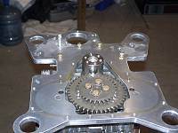
The rear plate is machined from a light alloy plate. We can make out the trace of the timing gear housing, sealed with Loctite 515, as well as its two positioning dowels.
On the crankshaft end, the 6 tapped holes for the flywheel screws, and the small bore of the pinion indexing pin.
In the forefront, the large 44 tooth camshaft gear, the thinner pinion above is the distributor drive gear (30 teeth).
Near the s/n two timing marks are showing in white.
In the corners, the 4 silent blocks mounting lugs are integral with the rear plate, which also shows the starter motor aperture.
Timing gear
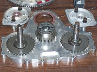
The gear housing is machined from a light alloy plate. The timing gear lip seal (50×65×8) is pink.
In front of the seal, the 22 tooth timing gear which slips onto the crankshaft end. We can see the 6 screw holes, and the 3 6×24 dowel bores, as well as the indexing pin maintaining the pinion on the crankshaft during assembly.
On each side on the housing, the two pinions (30 teeth) are riveted to the distributor shafts. Behind are the distributor cap mount plates, the left one showing its lip seal (15×24×7).
Flywheel
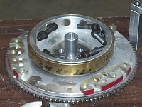
The flywheel has 3 assemblies of 3 15×7 rare earth magnets and pole plates, as the the engine has 6 cylinders (engines fires 3 times per revolution) .
In the middle, the alternator rotor has 12 cylindrical magnets, which have attracted some screws.
The internally splined part is the light alloy vacuum pump drive.
Alternator
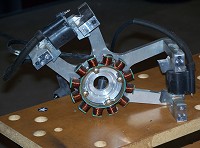
The spider stator mount standing on its 4 L-shaped mount blocks.
The black sleeve coming out of the spider protects the alternator leads.
12 pole stator on its spider mount. The two ignition coils are screwed to the 4 L-blocks through their pole plates.
Induction manifold
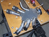
The 6 lower induction pipes are inserted into a fully machined two part plenum.
The manifold assembly is attached under the sump at the rear of the engine.
The rubber carburetor coupling is visible on the right.
To learn more
Jabiru seminar
 Send an email








 Jabiru USA Sport Aircraft

