Contrails ! Bosch VE injection pump
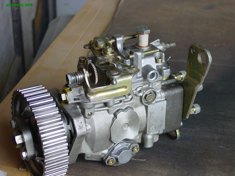
Homebuilts and Diesel
Homebuilders show much interest in Diesel engines : after developing the Dieselis with Paul Lucas, Serge Pennec designed the Gaz'Aile.
This aircraft was largely drawn from the Banbi-MCR familiy, with an inexpensive engine.
Reconditionning a Bosch injection pump
Bricofoy is a young electronics engineer, with a deep mechanical knowledge.
Diesel lovers will enjoy his remarkable study on the Bosch VE Diesel injection pump. The original article appeared in 2005 on Forum Auto, and is published here with his kind permission.
The Bosch VE injection pump, by Bricofoy
Click on images to enlarge
"Here was my occupation on last friday night : prepare a nice Bosch pump to install in a Peugeot 205.

The pump is in an undetermined state, so we're off for a reconditionning with a complete disassembly, change of seals and all.
And I did well, for it was filled with sludge.
Here is our starting point : a pump, suitable seal kit, control lever bushing and input shaft lip seal.

The same nearly one our later :
There's a lot of parts in a Bosch pump. There are still more in a Roto Diesel !
I didn't take pictures during dismantling, so just follow in reverse order if you have doubts about the disassembly ;-)
Needless to say, once the pump is in pieces, all the parts must be thoroughly cleaned. Further, liberally lubricating the rubbing, sliding or reciprocating parts with penetrating oil is an obligation during reassembly.
High pressure delivery valves
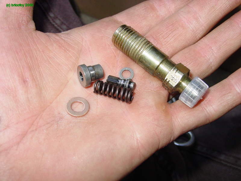
For starters, we will begin by reassembling the pressure head delivery valves. Here are the different components : valve, spring, adjusting spacer, nice brand new seal, and fitting.
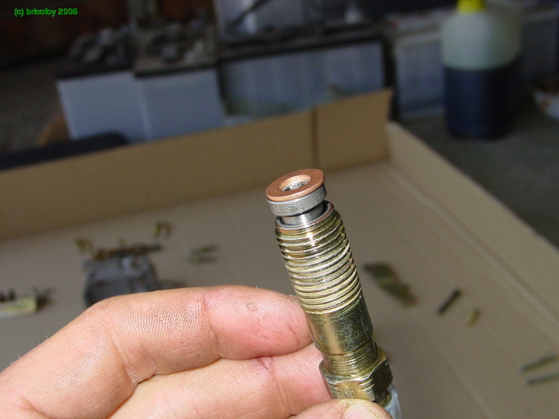
The parts are put together again :

Et hop :
Transfer pump
Now let's get to the real stuff :
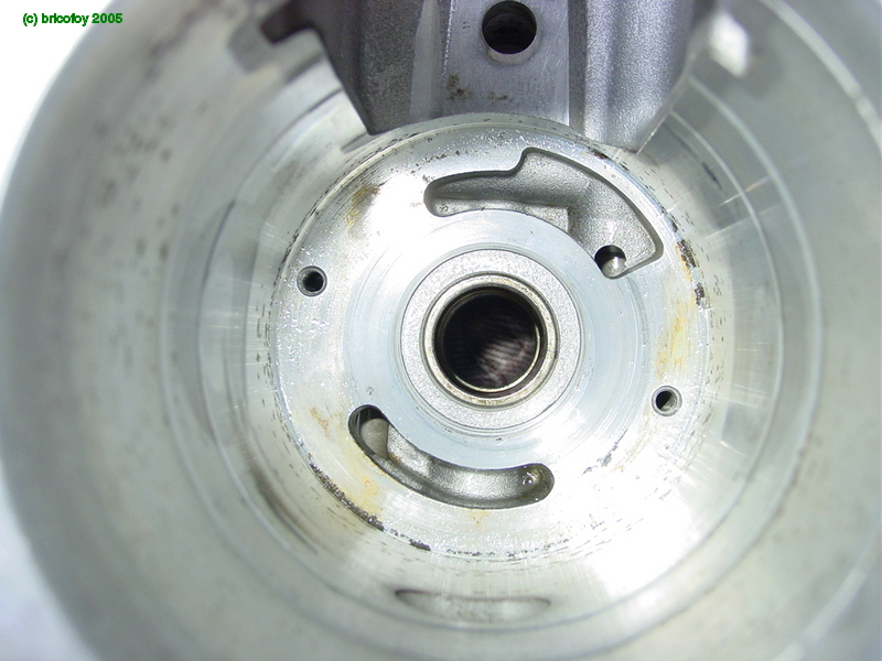
Hoooo, it's empty ! You can even see my jeans through the opening at the bottom :lol:

We begin by installing the transfer pump stator :

Make sure to correctly position the drilled holes in front of the threaded holes at the bottom of the pump housing (green circles).

Then the rotor and its vanes :

First the rotor :


Then inserting the vanes with round (and long) nose pliers :

Then the transfer pump cover plate :
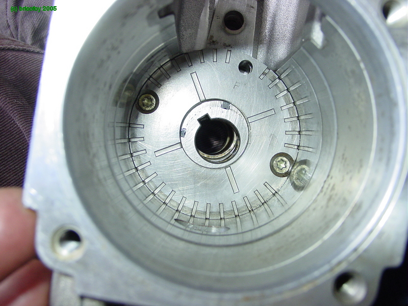
Now in place with its screws
Input shaft

We are now installing the input shaft :


Before putting it in its place, we must insert the governor drive gear and its two new elastic drive pads :

Next the washer that goes behind :

Finally the transfer pump drive key :
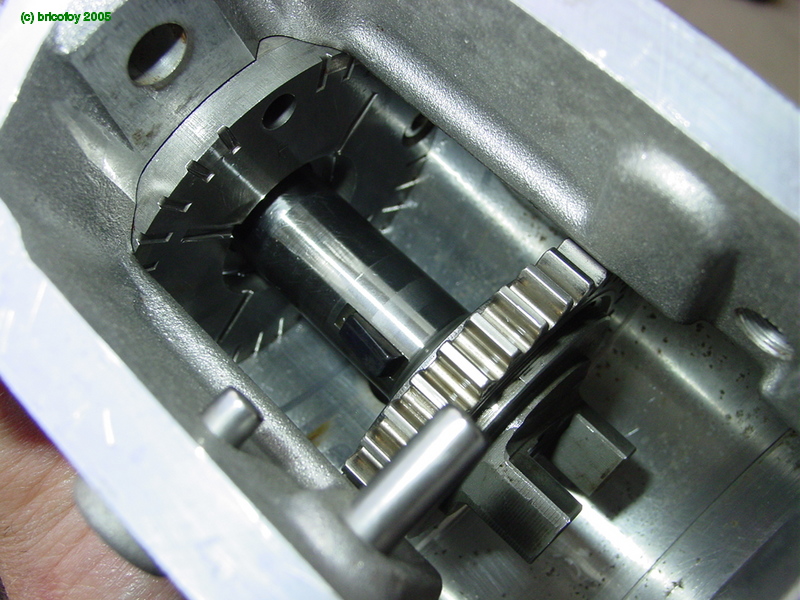
The whole assembly is now inserted into the pump housing :
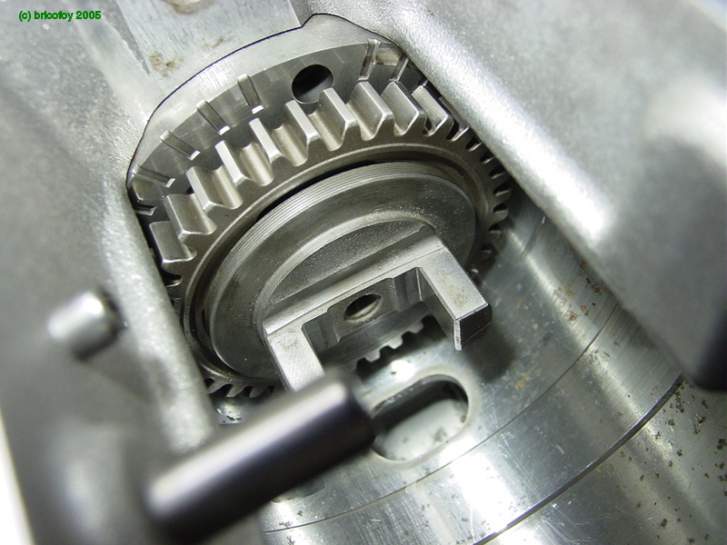

Here goes, fully home :
Roller carrier ring and face cam ring

Now we are reassembling the following : the roller carrier ring, with its drive pin for the timing mechanism.
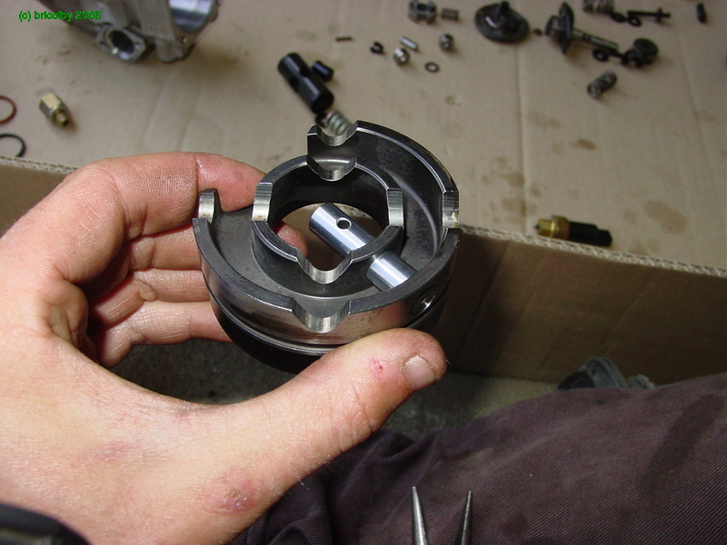
Inserting the drive pin into the roller carrier (caution, place the pin hole in the right position !) :


The assembly is then installed in the pump housing :
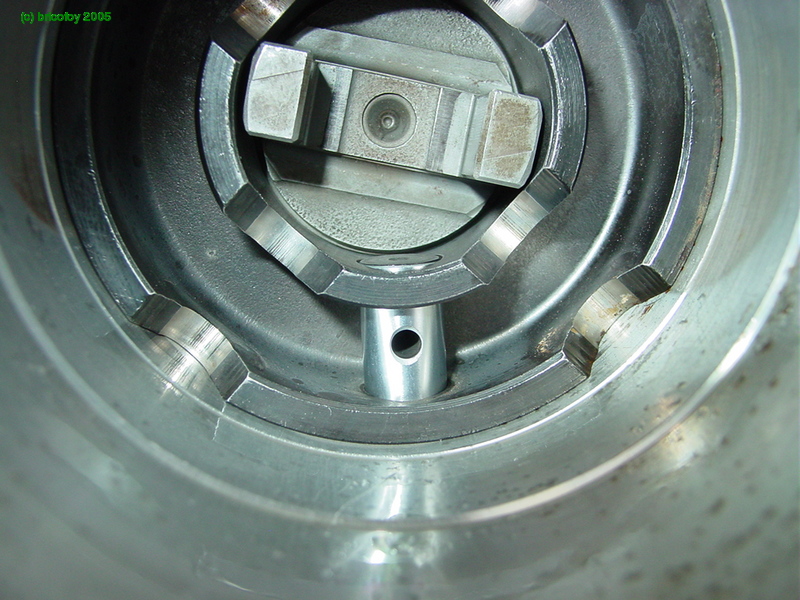
Here is where the drive pin goes when in its working position :


It protrudes into the timing piston cylinder :

OK, now we only have to slide it back into the roller carrier in order to install the timing piston :
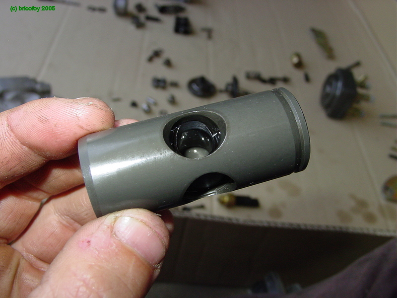
Reassembling the piston and trunnion :
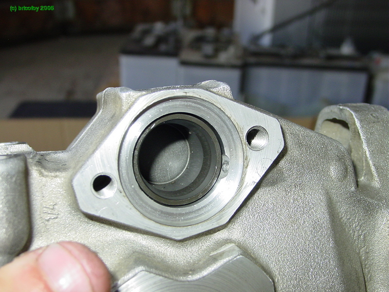
Next the piston is inserted into the cylinder :
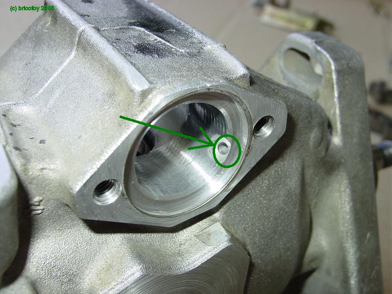
Mind the correct orientation ! The hollow spring housing must face the transfer pump communication port (green) :

Now sliding the drive pin back into position
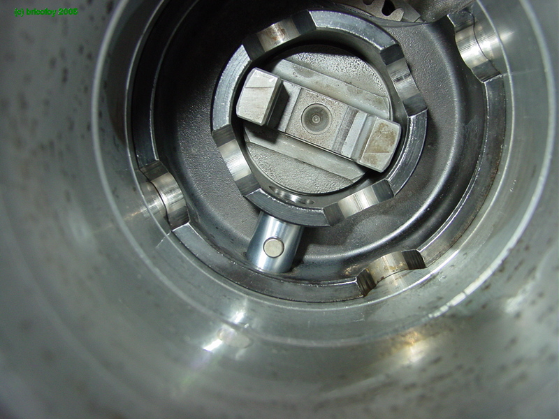

and lock it in position with the locking pin
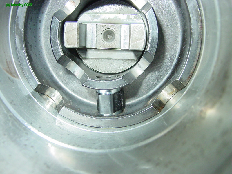

and secure it with the clip :

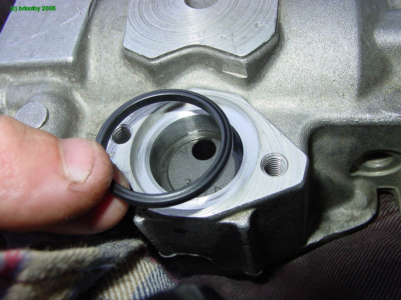
Now reinstalling the timing cover, with a new seal :


Next on the other side, the spring and electric cold start device :

I finally got rid of the cold start mechanism, since the 205 normally has none, and so doesn't have any cold start control. I replaced it with the regular cover :


Installing the four arm spider that drives the rest of the pump mechanism :

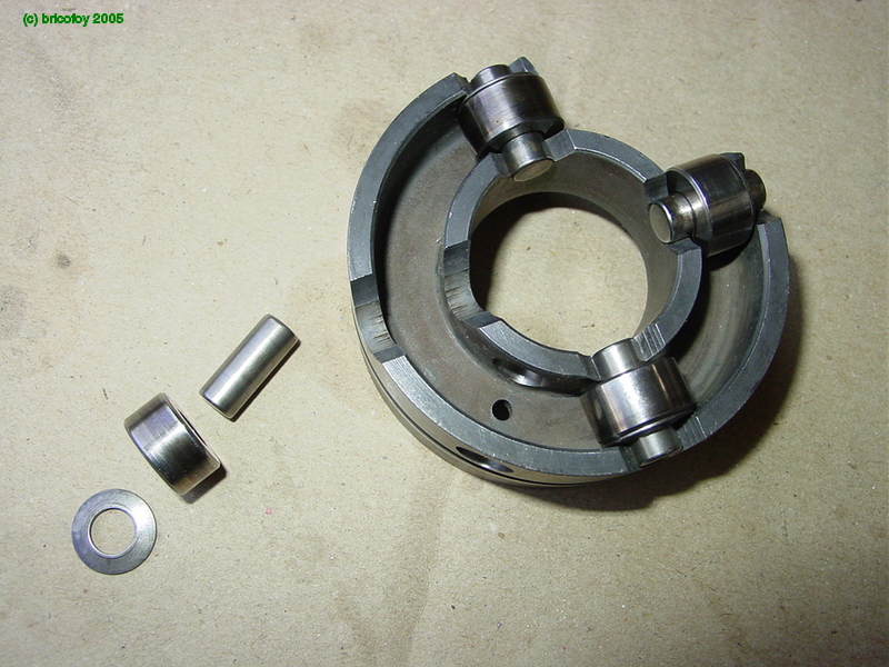
Next to the rollers. They are shown here outside of the pump : please note the orientation of the washer, which is convex to match the curvature of the carrier :
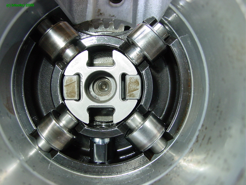


Next the spring in the center :

And the cam disk :

When installing this part, the plunger drive peg (green circle) must line up with the input shaft key.
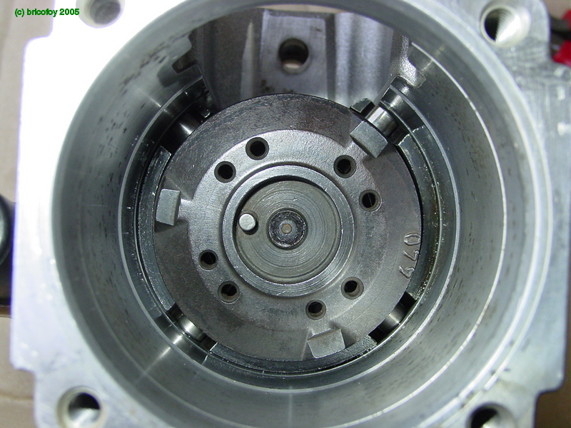
When riding the rollers, the face cams move the plunger axially, compressing fuel for injection. Timing is modified by rotating the roller carrier by means of the timing piston located beneath.
Here I changed the cam disk, since the one which came with the pump doesn't have the same profile. The new one comes from a 205 injection pump.
Distributor plunger

Now the distributor plunger :

We then add the control sleeve.
Under the control of the regulator levers, the sleeve slides and variably covers the plunger spill port (green circle on previous picture).
During injection, the plunger moves axially under the thrust of the cam disk. According the control sleeve position, the spill port is uncovered when the plungers slides, after a variable portion of the stroke. Thus the injected fuel is metered (when the spill port is uncovered, high pressure fuel escapes, and injection ceases).
The plunger is named "distributor" because it revolves and directs fuel to each delivery port, via its slits and channels.
High pressure head

We now insert the distributor plunger into the high pressure head :


next the springs :
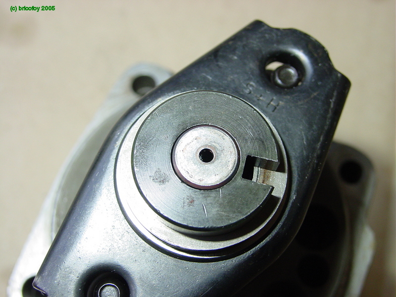
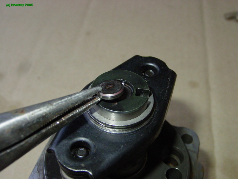
The spacer at the end of the plunger :


and we put everything back together into the pump :
Governor speed levers

We will now reassemble the governor speed levers and springs :

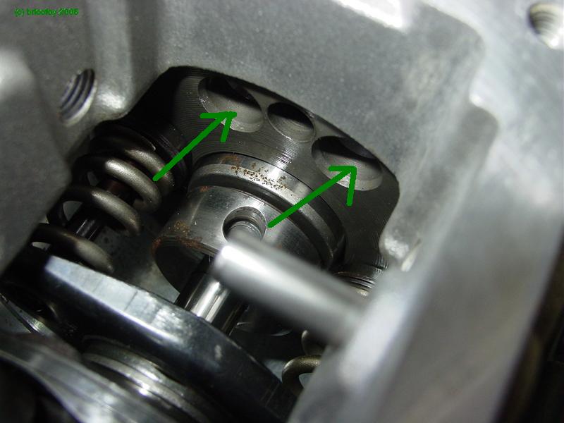
The installation is tricky due to the spring position :

Detail of the lever pivot with special screws (I made a purpose socket by grinding an old 13 mm socket)

Installing screws with new aluminium seals :

We just have to insert the lever assembly from above :
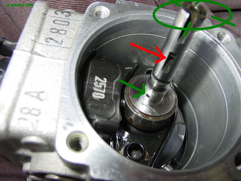
Shucks, no way ! ... We have to remove the pressure head and insert the levers BEFOREHAND ![]()
By the way, please note on the plunger, the spill port (green), distributor slit (red), and the 4 metering slits at the end (green). The plunger is hollow to connect everything.

The high pressure head with all the springs in place :
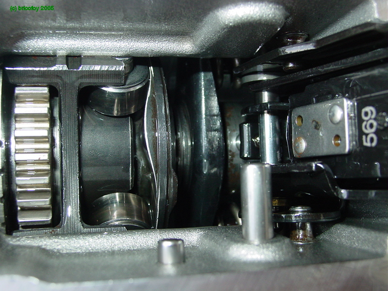

We just have to reassemble the whole thing, then remove it once or twice because the springs won't fall in place, and voila :
Governor
Let's now see the governor.

Here are the parts :


Assembling the fly weights :

Replacing the fly weights into the governor :


Then placing the governor sliding sleeve (please note the calibrated port for governing the injection timing according to engine load)
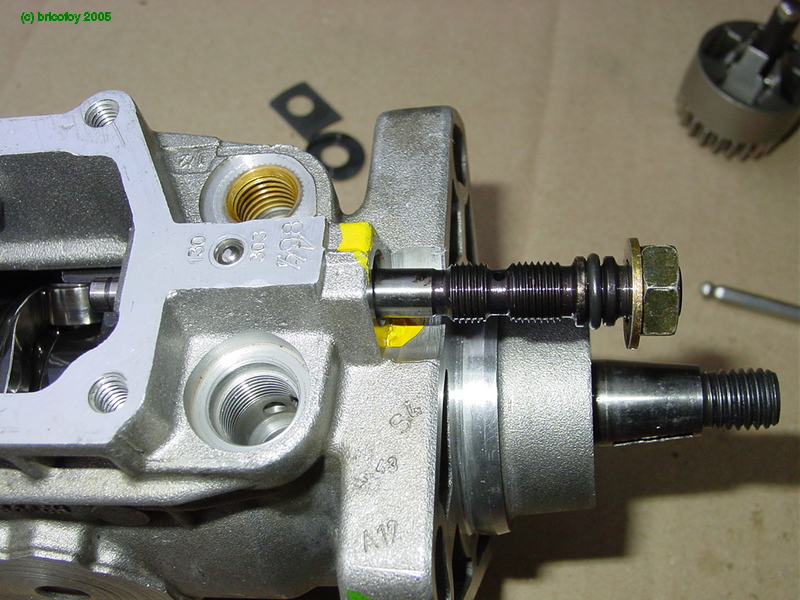
Then installing the governor shaft into the pump housing :


Those wahers go behind the governor assembly :


Then the governor itself :

We now insert the shaft into the casing, and tighten it with an Allen wrench and an open wrench, to hold it in position while tightening the locknut.
The shaft position is key, as it commands the injection timing. Make sure its position is adequately marked when dismantling :
Governor cover
Voila, now the pump assembly is complete, we just have to reinstall the case cover, and the transfer pressure regulating valve. I could have installed the valve before, but...


We first drive out the old control lever bushing :
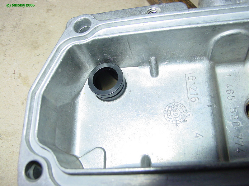
Then we replace it with a brand new bushing :


Carefully driving it home with a a bolt and large washers :

Next installing the command shaft and speed control springs :

Close up of the hooking up of the speed control springs onto the governor levers : the flat (green) is inserted into the lever notch (red) then pulled back home :
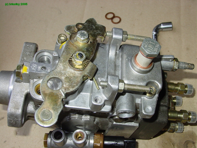

Et hop, we just have to replace the cover (with a new seal) and secure it.
We now reinstall the accelerator lever, taking care to put it back in its original position with regard to the markings on the shaft and lever (of course make sure you carefully mark the correct position during disassembly).
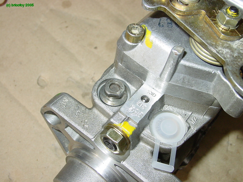

Now reinstalling the transfer pressure regulating valve (of course with new seals) :

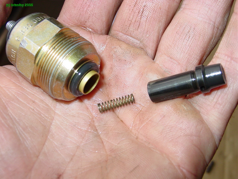
Next the solenoid actuated fuel shut-off valve :

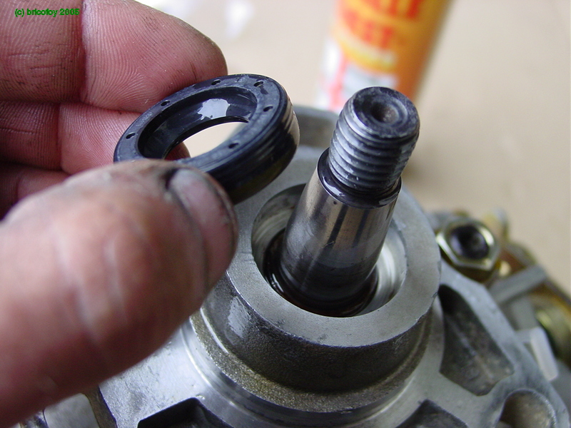
Finally the input shaft lip seal (it is installed with a large socket and driven home by screwing the pulley nut onto the shaft).
Sorry, no photo.

And voila, we're done. All we have to do is bolt it into the Peugeot 205 ! :-)"
With kind permission of Bricofoy
 Send an email to Bricofoy


 Serge Pennec's Gaz'Aile website


