- Home
- Electricity
- Rotax/Ducati
Contrails ! Rotax/Ducati alternator & regulator
This "beta version" will be updated in the future.
Background
The Rotax/Ducati rectifier-regulator supplied with the Rotax 91x engines exhibits an alarming rate of failure among homebuilt aircraft.
In order to sort out the reliability issue before installing it in our MCR 4S four seater kitplane, I succeeded in putting my hand on a complete Rotax alternator, just in case...
The pieces were waiting a hypothetical test in my garage, until I met Jérôme Delamarre, a young electricity professor and researcher at LEG (Electrical Laboratory of Grenoble), University of Grenoble, France.
Brief description
Jérôme is an MCR lover, and he soon proposed his help to test the alternator and his regulator.
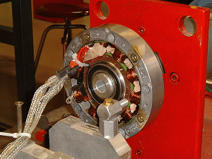
Jérôme machined an adapter to install the regulator on a test bench in one of his students laboratories.
We spent several weekends conducting tests.
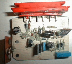
The regulator
In the meantime, Dyn'Aero sent two failed regulators. I took them to pieces, removing the foam to identify the components.
Jérôme studied the principles of the regulator.
At the time (winter 2003), we had difficulties founding specs for the TPE154E SCRs. Jérôme had to run them on a test rig in his laboratory.
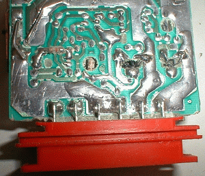
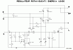
Regulator diagram
Here is a diagram, redrawn after our previous study.
There have been lots of questions on the Internet, as to whether the Rotax regulator is shunt or else.
The Rotax regulator is not of the shunt or series type.
Please note
This diagram was redrawn from hand sketches taken two years ago. It is offered as-is, for information purpose. It may contain errors.
When -and if- time permits, I'll retrieve the dismantled units, and check its accuracy.
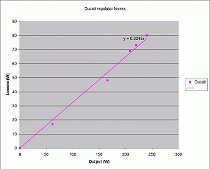
Regulator losses
The regulator losses have been measured, and are proportional to the output, as indicated on the curve taken by Jérôme's students
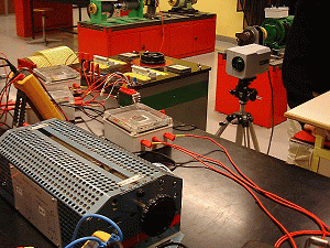
Thermal tests
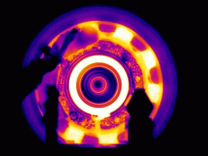
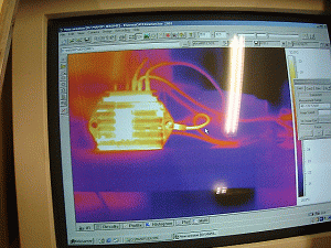
The students continued with a thermal study.
Here we can see the thermal camera, used to identify hot spots.
Rotax documentation specifies an ambient temperature limit of 90°C. This seems doubtful.
At nominal output, ie at 240 W, the regulator dissipates 80 W (actually measured)
- Thermal resistance between the regulator heat sink and and the ambient
atmosphere, measured at sea level, is 2°C/W.
- In a simplified way, one can add a series thermal resistance of 0.3°C/W to obtain junction temperature.
- Junction temperature must not exceed 125°C.
Conclusion
In order to work at nominal output, the ambient temperature at sea level should not exceed :
Using the regulator at nominal output without further cooling seems impractical.
Why no failure ?
Many homebuilders may not experience regulator failures
There are two reasons :
- Many use but one tenth of the nominal power advertised by ROTAX.
- It takes 45 min for the regulator to reach its max temperature (thermal time constant on the order of 15 min)
Cooling
With a PC type fan, the regulator heat sink thermal resistance drops to about 0.5°C/W. At sea level and nominal output, the ambient temperature needs to stay below :
Much more reasonable.
 Contact the author


